Introduction
As part of the implementation section for my final-year Internet of Things course during my undergraduate degree, the decision was made to create a camera system that can alter its viewing angle remotely. This type of device brings an added dimension of versatility to security cameras by allowing a single camera to cover a much wider area than what would be otherwise possible without distorting the image with accessories like a fisheye lens. To achieve this, the project will make use of an internet-connected microcontroller that will host a webpage displaying a live camera feed and an array of buttons that send movement instructions to the microcontroller to be acted on by the servo motors. This project aims to create a system that can display low-latency video of acceptable quality for security purposes while also providing a robust movement system that is all accessible in a simple user interface.
Project Hardware
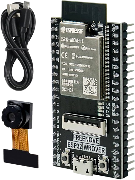
The microcontroller selected for this project was the ESP32-WROVER CAM. This board was an ideal choice for this project due to the versatility of the ESP32 microcontroller for IoT applications and the inclusion of a camera module and Wi-Fi antenna to streamline circuitry significantly by removing the need for separate hardware to achieve the same functionality. Furthermore, the ample amount of GPIO pins facilitated the easy expansion of extra hardware, while an inbuilt USB to serial chip provided a heightened level of convenience by allowing the upload of code to the board directly through the USB port rather than requiring an FTDI programmer.

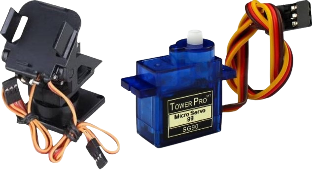
To provide the movement element of this system, the SG90 mini servo was chosen to be used in conjunction with a pan-tilt gimbal. This servo is a popular choice in maker communities due to its ability to provide granular movement control while maintaining a compact form factor and low power requirements, properties that were conducive to this project by alleviating the need for any external power sources, making the system both easily portable and simple to power via battery. This project utilises two of these servos attached to the aforementioned pan-tilt gimbal to translate the rotational movement of the servos to a two-axis movement platform from which the ESP32 can be attached.

Project Software
Camera Setup
Natively, Micropython doesn’t include the necessary driver to make use of the camera module that is an essential part of this project, so to remedy this issue, it became a requirement for custom firmware to be flashed onto the board that included the required camera driver to allow for operation from within the code. For simplicity, this project made use of the precompiled camera-focused firmware from LeMaRiva that, after a simple flashing process, gave full access to the OV2640 camera through the ‘camera’ library.
| |
To initialise the camera ready for use later on in the program the ‘camera_init’ function needs to be called. This function takes several parameters, including a list of the GPIO pins that the camera module is linked to, and performance settings for the camera feed such as resolution and clocking frequency. Information about the GPIO pin configuration was readily available through the board manufacturer documentation and the performance of the camera was kept modest with a VGA resolution and clocking frequency of 10MHz so as not to overwhelm the limited computing power of the ESP32 while still maintaining a smooth and somewhat detailed image. The final parameter ‘fb_location’ determines where the frame buffer will be stored; PSRAM was selected for this purpose as the balance of speed and capacity it provides make it most suitable for this application.
Web Server Setup
| |
With access to the camera accomplished, focus could be shifted to the web server that acts as the foundation for the camera’s control and monitoring system. This began by establishing a network connection using the ‘network’ included with micropython which provided the functionality for seamlessly working with network connections in MicroPython and provided configuration options for the ESP32 to operate as either a station or an access point. While both of these choices would be functional, the choice was made to implement the ESP32 as a station since using an access-point configuration would limit the range of the system to the range of the ESP32 antenna whereas a device operating as a station can be configured to be accessible from anywhere where an internet connection is available which is much more useful for a security camera. Network credentials were handled through a separate file named ‘config.py’ to detach sensitive information from the main codebase, this file is called by the ESP32 during connection attempts where five seconds are allocated for the connection to be established, otherwise, the connection attempt is deemed to have failed.
With a network connection established, a web server can now be set up. It is essential that the web server can accept asynchronous requests to facilitate the constantly updating video feed without requiring a page refresh. A common way of achieving this is through the ‘asyncio’ library which provides powerful general-purpose async operations to Python. However, the power and functionality provided by asyncio goes beyond what is required for this project and so a more elegant solution is a web-focused framework such as ‘picoweb’. This framework was purpose-built for handling network requests on microcontroller devices like the ESP32 and enjoys advantages such as simple configuration and computational efficiency as a result, making it a much more fitting choice for this project.
| |
To set up the web server for incoming requests, each URL that is expected to receive requests must be linked to a function. In this instance two types of requests are expected, those directed at the root URL, which is responsible for displaying the webpage interface, and those directed at the stream URL, which provides the asynchronous streaming of live video from the camera module to the web page. To address this, the functions ‘index’ and ‘stream’ were created to hold the logic required to handle the requests from these URLs appropriately.
Video Streaming
| |
To set up the web server for incoming requests, each URL that is expected to receive requests must be linked to a function. In this instance two types of requests are expected, those directed at the root URL, which is responsible for displaying the webpage interface, and those directed at the stream URL, which provides the asynchronous streaming of live video from the camera module to the web page. To address this, the functions ‘index’ and ‘stream’ were created to hold the logic required to handle the requests from these URLs appropriately.
The function for handling the live transmission of video is quite straightforward, it begins by initiating a multipart response via picoweb, which directs new data to take the place of existing data within an ongoing response, and is followed by an infinite while loop that continuously applies the relevant headers and formatting to a newly captured image so it can be asynchronously transmitted to the web server for live viewing.
Servo Control
| |
To be able to control the servo motors, they first must be initialised. Although there isn’t a readily available library for convenient servo control in MicroPython as there is in Arduino, it’s still possible to control the servos using pulse width modulation (PWM) duty values instead. To achieve this, two variables are first created to keep a running track of what position the servo is in, and then two corresponding PWM objects are created that represent the GPIO pin each servo is connected to on the ESP32. Using these object variables, servo properties such as duty can be freely controlled through commands built into the PWM library.
| |
The main body of the servo control exists within the index function of the program as it is expected that all servo control will be managed through the web interface. Upon receiving a POST request, the relevant servo will be moved by a predetermined amount with ‘up’ and ‘down’ requests controlling tilt, while ‘left’ and ‘right’ requests control pan. Each conditional statement also incorporates checks to ensure the servo duty remains within a safe operating range to prevent damage to the servos that could render the system inoperable. The movement of the servos is then broken down into a ‘for’ loop which adds a 20ms delay between each duty value update to provide a smoother panning experience as it was found that the servo moving to its end destination at full speed was quite jarring in practice.
User Interface
| |
As alluded to earlier, the user interface is fleshed out using HTML in a web environment. The most prominent feature of the page is the video feed provided by the ESP32 camera, which is powered through an image tag linked to the ‘/stream’ URL that as mentioned previously will constantly provide an up-to-date image of what the camera module sees. The second part of the interface is the control buttons; Each one of these buttons calls a function when clicked that sends an asynchronous POST request containing the cardinality of the button under the variable name ’direction’, this is what the conditional statements in the index function are using as comparison to determine what servo to move and in what direction.

Final Product
The result of this project is a plug-and-play system that will begin operations immediately after receiving power. While operational, users can visit the IP address assigned to the device to view the live video feed from the camera while also being able to influence the direction the camera is facing up to two times in each direction by using the arrow buttons provided by the web interface. With further network configuration, users can also set up this device to work remotely through methods such as port forwarding or a local VPN.
Overall, the project achieved what it originally set out to do, provide wireless access to a video feed while allowing for the ability to remotely change the camera’s angle. However, there were certain limitations that should be addressed should the project be revisited. Firstly, Overall, the project successfully met its main objectives, though there are areas for potential enhancement. The video streaming delivered clear VGA resolution with minimal latency, suitable for live monitoring. However, the image quality wasn’t top-tier due to hardware limitations of the ESP32 and MicroPython’s runtime performance. Future improvements could involve using a more powerful microcontroller or faster firmware like NodeMCU to enable higher quality streaming. The two-axis camera control was also effective, with SG90 servo motors providing accurate and smooth motion across a wide range, fulfilling the goal of large coverage. However, the motors were somewhat noisy, and the plastic pan-tilt gimbal’s lightweight design made the setup prone to toppling, suggesting a need for quieter motors and more robust materials for stability in future iterations. Finally, the user interface was simple to use and easily accessible through its web interface. However, there was still room for aesthetic improvements to make the user experience more enjoyable